Texturing and Modelling Chapel Tiles
- Feb 1, 2019
- 9 min read
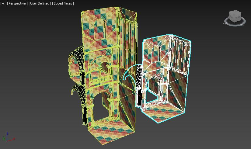
In my last blog post, I mentioned that I finished modelling the ‘three_story_concave_corner’ tile, with the UV’s sorted and material ID’s assigned ready for texturing. During the week after this blog post, I finished modelling the two story version of the concave corner, along with unwrapping UV’s, assigning material ID’s and finishing the texturing for these tiles. I was able to finish all of these tasks in one week as I was able to just remove the triforium area of the ‘three_story_concave_corner’, then I could snap the clerestory area onto the nave area to create the ‘two_story_concave_corner’. As the UV’s and material ID’s were already finished, I just had to weld the vertices of the new tile together and work through the xView checks, ready to be textured.


Towards the end of week 10, I realised that I had also planned to model the tiles in Image 4 which I discussed in my third blog post called “Planning the Modular Tiles”. So As well as texturing for the tile in image 3, I also had to model, UV unwrap and texture the tiles in Image 4 if I were to stay updated with my milestones. I started off week 11 by texturing the tiles in Image 3 by using the Smart Materials that I had made for previous tiles. This was a very quick process and I didn’t have time to add any fine details such as cracks in the wall or extra dirt marks for these tiles. I’ll be adding finer details in the textures if I find some spare time throughout the project.
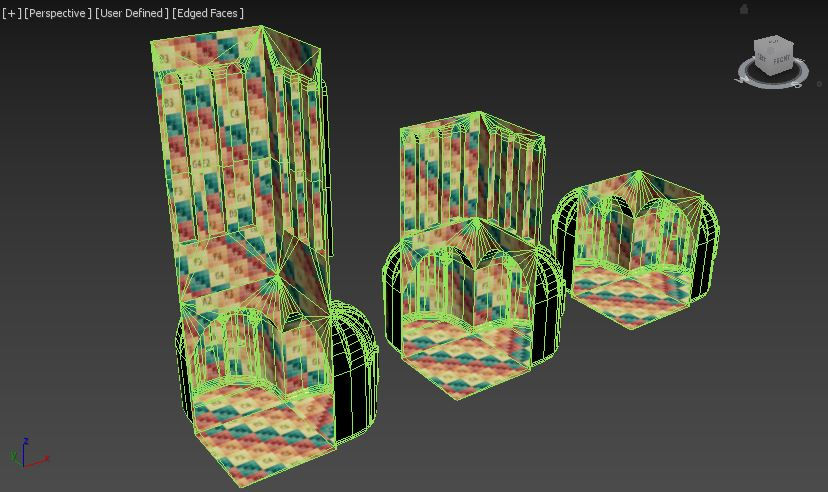
Once the tiles found in Image 3 were finished, I began modelling the tiles in Image 4. I started with the next tile on my list, the ‘three_story_deadend’ tile, where once again most of the tile could be duplicated from the ‘three_story_open’ tile I had previously finished.

Once I had the base of the tile ready, I added in walls on the right side of the open ended tile, to make a dead end for the aisle and triforium. This was done my using the create tool and connecting edges to avoid Ngons. The UV’s were then flattened and arranged into their own material ID’s.

Secondly, I added more walls to the right so I could close off the tile entirely on one side, to be used at the transept ends. I used one of the photos I took from the trip to St Albans Cathedral, where you can see long, thin windows at the end of the transept. I thought this would work well to bring enough light into the church when building the variations for rendering and marketing images. I duplicated the window from the clerestory of the ‘three_story_open’ tile, and attached it to the wall of this new tile. I resized the window in accordance with my reference photo and duplicated it three times to fill out the space in the walls.
St Albans transept windows

Once the ‘three_story_deadend’ was modelled with flattened and arranged UV’s, assigned material ID’s and correct smoothing groups, I was able to duplicate this tile to start the ‘two_story_deadend’ tile. Once again, I removed the triforium area to create a two story version. The windows were resized to fit this smaller version, and the UV’s and material ID’s were rearranged more efficiently.

With these tiles finished, I moved onto the straight and corner variations. I started with the ‘three_story_straight’ tile, as all I needed to do was duplicate the wall I had made for the dead end tile, and straighten out the left edges. I had ‘Preserve UVs’ enabled while doing this, so that the texture wouldn’t warp while I moved the faces on the model. I added in another window and spaced out the rest of the windows, so that when placed together, these tiles would have a similar amount of space between the windows. To create the corner variation, I duplicated the wall of the dead end tile again, duplicated this again without the floor, mirrored it on the x-axis, then snapped the two pieces together. Once the tiles were welded together, it showed up on the x-view checks that the ‘Face Orientation’ needed to be fixed. I did this by resetting the X-form, then once I collapsed the stack back to an editable poly, the faces were facing the wrong way. To fix this, I then had to flip the faces, which then meant that the UVW faces were flipped. This was easily solved by selecting the flipped faces and mirroring them in the UV editor. This whole process was repeated with the two story versions to make the straight and corner tiles.
Once these tiles were modelled with the correct UV layouts, material ID’s and smoothing groups, I textured all of these tiles with the same Smart Materials that I had previously made. I was able to texture two of these tiles in the time I had left in week 11. I spent most of the day at the beginning of week 12 getting these tiles textured and again I didn’t put many finer details in the textures as I was now behind with my milestones and needed to make sure that I had enough time to produce the chapel variations found in Image 5.

In my second blog post, I included a moodboard which shows floor plans of a Latin Cross architectural typology. I found that there were a series of radiating chapels in the eastern part of the church, mostly attached to the ambulatory but also at the sides of the transept areas. Radiating chapels were “generally located off the back of the church behind the altar where relics were often displayed.” (Bolli, 2019) I also found out that “radiating chapels of Romanesque churches fulfil the dual function of supporting the upper arches and providing a space in which regular parish members might pray in the central nave or around the altar.” (Bloch, 2019, 06:14:00) I planned out a few variations for the radiating chapels, to add versatility to my modular tiles. I have developed another moodboard consisting of the ambulatory with radiating chapels, to inform my design as I model these tiles.


I started off by creating the chapel itself, which would be used for all of these tiles. I duplicated a ‘two_story_open’ tile with an ‘aisle’ tile attached, so that I’d know that what I am modelling will properly snap and fit to the chapel tile I was working on. I used the groin vault in the ‘two_story_open’ tile to place on the base chapel tile for the same reason. I duplicated the columns of the ‘aisle’ tile and snapped them into the desired place on the base chapel tile. I then connected the horizontal edges of the semi-circular structure of the chapel wall and extruded the faces at the bottom to create a skirting that would meet with the columns. I extruded the edges of the vault to the back on the chapel, but decided this was not the shape I was looking for.

While observing my moodboard of chapels, I duplicated the columns again, reduced the size and adjusted the shape to fit on to the back wall of the chapel. I then went into ‘Compound Objects’ and used the ‘Boolean’ tool to combine the column and wall together, creating a single object. This made the process of attaching the two objects a lot easier, deleting any unwanted, overlapping faces, edges or vertices. After tidying up this column, I could then duplicate this section and rotate it to fit the section next to it. I continued with this process until there were four columns around the chapel. I then wanted to bend a second group of columns on top of the ones I had just made, to create a dome shape for the ceiling. I extruded shapes from the top of the columns, pondering how to produce this part of the desired geometry.

I decided to create a cylinder, similar to the size of the columns I wanted to bend and added a few height sections in. I then used the ‘Bend’ modifier and checked that the dimensions were correct where it would be placed. I adjusted the parameters of the modifier, then collapsed the stack back into an editable poly. I could then duplicate this new object three times, then rotate and move each one to fit on top of the columns. The next part was extruded from these objects to add a section that would connect the columns to the wall and ceiling. I then deleted the top part of the wall and created faces between the gaps of the column edges to create a curved ceiling.

After the main structure of the chapel was finished, I used the create tool for the floor and then moved onto the windows. I duplicated a window that I already made for other tiles and reduced it in size to fit the walls of the chapels. I then worked through the xView checks, checked for Ngons and assigned smoothing groups to the chapel tile. I proceeded with the UV unwrapping, assigning material ID’s as I went. With this ‘aisle_straight_chapel’ tile finished, it could then be used in all of the other tiles I would be producing this week.

To create the ‘two_story_straight_chapel’ and the ‘three_story_straight_chapel’ tiles, I used parts of the tiles I created in the previous week and attached these parts to the ‘aisle_straight_tile.’ Again, this meant that UV’s, IDs and smoothing groups were already sorted, I just had to attach the two parts together and double check the xView checks.

Finally, I moved onto the corner variations of the chapel tiles. I duplicated the original chapel part again and found that it was slightly too big for these tiles. I realised then that it would’ve been easier to create the chapel at the size of this base tile first, because it would fit with the other, wider tiles. As I had to downsize this radiating chapel for the corner variations, some of the UV’s became warped and moved outside of the 0-1 boundaries. It took me longer than I expected to finish these tiles for this reason. I was able to duplicated the previous tiles I made in Image 4, to use on parts of these corner chapel tiles. Then once each right version was made, I could mirror them (following the same procedure that I did earlier with the three/two story corner tiles) and within a few minutes I had three more tiles finished.

Finally, to make the three corner variations with two chapels on each tile, I used the previous tiles by duplicating and mirroring the parts I needed. All I needed to add to these tiles was a middle section that would connect the skirting of both sides. The UV’s, ID’s and smoothing groups were mostly finished so it didn’t take long to complete these variations.
As I was applying materials to the object I made, I started to realise that I didn’t need a separate material for each tile. I was originally doing this so that I could name each material ID in 3DS Max, so that when I opened the object in Substance Painter, I would know what each texture set would be. Instead, I could assign the same material with any name to each tile, making sure that there were enough material slots to match the amount of the objects ID’s. Then I could rename the texture sets in Substance Painter, ready for exporting to Unity.

In this series of photos you can see how I organised the textures when there are windows within a mostly stone texture set. I applied the ‘Stone’ Smart Material to this texture set, then dragged the ‘Window’ Smart Material on top. In the first photo you can see that I added a black mask to the ‘Window’ Smart Material, which makes the texture hidden. I then used the ‘Polygon Fill’ tool to select each window UV face, which makes this ‘Window’ Smart Material visible on the selected faces. This also means that the ‘Stone’ Smart Material becomes visible underneath, so to fix this, I applied a white mask to the ‘Stone’ Smart Material and selected the same window UV faces. This makes sure that the materials are set to the correct UV’s. You can also see these changes happening on the model on the left side of the screen.

In the photos above, it shows that the connecting parts of the curved pillars are a darker colour. I made a new layer, and used the ‘Polygon fill’ tool again to select these faces, and pick a colour that would help separate these parts of the architecture, to make it stand out more.

Within most of these tiles, there are areas that aren’t automatically seamless, which has to be fixed by moving the texture in the correct place. In the photo above, I have corrected the right side of the wall by finding where the details in the texture come together, whereas on the left wall you can see a seam where the texture doesn’t meet perfectly.
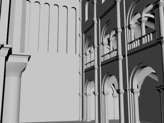
Although the amount of detail in texturing was compromised, I was able to get all of these tiles finished, even after missing the tiles I should’ve made sooner. I am fully up to date with my milestones again and I even had some spare time to build an environment to test the finished models so far. I realised that I will need to make mirrored versions of ‘three_story_deadend’ and ‘two_story_deadend’ tiles, as they will currently only attach to one side of an open tile. These will be renamed with ‘_left’ and ‘_right’ at the end of the tile names. I will add these tiles into next week’s tasks when I start modelling the next set of tiles. I have taken a few renders of my current progress with the models, using different tile variations for the chapels, size of the nave and transepts, and various points of view.
renders


Bibliography
Bloch, H. (2019) “The Age of Cathedrals” [Online Video] Available at: https://www.coursera.org/lecture/age-of-cathedrals/6-1-romanesque-9LWfj [Accessed: 31 January 2019]
Christine M. Bolli (2019) “Pilgrimage Routes and the Cult of the Relic” [ONLINE] Available at: https://www.khanacademy.org/humanities/medieval-world/romanesque1/a/pilgrimage-routes-and-the-cult-of-the-relic [Accessed 31 January 2019]
Photo References
Arth 109 (2019) “ambulatory” [ONLINE] Available at: http://employees.oneonta.edu/farberas/arth/arth109/arth109_sl19.html [Accessed 31 January 2019]
Arth 202 (2019) “choir_exterior” [ONLINE] Available at: http://employees.oneonta.edu/farberas/arth/arth212/romanesque_arch.html [Accessed 31 January 2019]
Fyletto (2018) “romanesque-chapel-stock-picture-661973” [ONLINE] Available at: https://www.featurepics.com/online/Romanesque-Chapel-661973.aspx [Accessed 31 January 2019]
Inglis, E (2019) “366-117” [ONLINE] Available at: http://www2.oberlin.edu/images/Art336/Art336e.html [Accessed 31 January 2019].
Siepmann, M (2012) “frescoes-in-the-romanesque-charnel-house-hartenberg-east-styria-styria-CXT398” [ONLINE] Available at: https://www.alamy.com/stock-photo-frescoes-in-the-romanesque-charnel-house-hartenberg-east-styria-styria-50931252.html?pv=1&stamp=2&imageid=C8A50E35-2B4C-4A85-92ED-19187FABDD9A&p=5530&n=0&orientation=0&pn=1&searchtype=0&IsFromSearch=1&srch=foo%3dbar%26st%3d0%26pn%3d1%26ps%3d100%26sortby%3d2%26resultview%3dsortbyPopular%26npgs%3d0%26qt%3dromanesque%2520chapels%26qt_raw%3dromanesque%2520chapels%26lic%3d3%26mr%3d0%26pr%3d0%26ot%3d0%26creative%3d%26ag%3d0%26hc%3d0%26pc%3d%26blackwhite%3d%26cutout%3d%26tbar%3d1%26et%3d0x000000000000000000000%26vp%3d0%26loc%3d0%26imgt%3d0%26dtfr%3d%26dtto%3d%26size%3d0xFF%26archive%3d1%26groupid%3d%26pseudoid%3d%26a%3d%26cdid%3d%26cdsrt%3d%26name%3d%26qn%3d%26apalib%3d%26apalic%3d%26lightbox%3d%26gname%3d%26gtype%3d%26xstx%3d0%26simid%3d%26saveQry%3d%26editorial%3d1%26nu%3d%26t%3d%26edoptin%3d%26customgeoip%3d%26cap%3d1%26cbstore%3d1%26vd%3d0%26lb%3d%26fi%3d2%26edrf%3d%26ispremium%3d1%26flip%3d0%26pl%3d [Accessed 31 January 2019]
TREKEARTH (2019) “wall_and_vault” [ONLINE] Available at: https://www.trekearth.com/gallery/Europe/France/South/Midi-Pyrenees/Toulouse/photo1397610.htm [Accessed 31 January 2019].


Comments